IN THIS ARTICLE
Create a Custom Tool Gem in Python to Extend Open 3D Engine Editor
In this tutorial, you’ll learn how to extend the Open 3D Engine (O3DE) Editor using the PythonToolGem template to create a custom tool Gem called MyPyShapeExample. This custom tool allows you to create entities with a Shape component and configure their component properties. The Gem is written in Python with
Qt , the O3DE Tools UI API, and other O3DE APIs.
The PyShapeExample Gem, a sample Gem in the
o3de/sample-code-gems repository , demonstrates the finished Gem that you create in this tutorial. You can reference the PyShapeExample Gem sample as you follow along this tutorial.
By the end of this tutorial, you’ll be able to extend the Editor by creating your own custom tools written in Python.
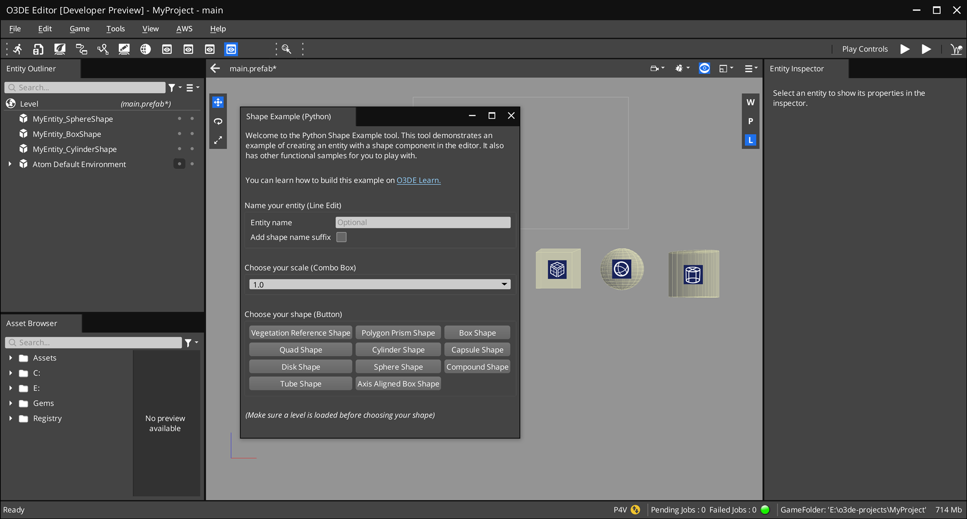
The following image is a preview of the custom tool that you create.
Prerequisites
Before you start the tutorial, ensure that you have the following:
- Set up an O3DE development environment. For instructions, refer to Set up Open 3D Engine.
Tutorial specifics
This tutorial uses the following Windows directory names and locations in the examples. You may choose different folder names and locations on your disk.
O3DE engine directory:
C:\o3de
The source directory that contains the engine.PythonToolGemtemplate:C:\o3de\Templates\PythonToolGem
The Gem template that your custom Gem is based off of.MyPyShapeExample Gem:
C:\o3de-gems\MyPyShapeExample
Your custom Gem. You may choose a different folder name and location in disk.
Create a Gem from the PythonToolGem template
Start by creating a Gem from the PythonToolGem template, which contains a basic Python framework to create a dialog window that extends the Editor.
To create a Gem based on the PythonToolGem template, complete the following steps:
Create a Gem by using the O3DE CLI (
o3de) script that’s in your engine directory.scripts\o3de create-gem --gem-name MyPyShapeExample --gem-path C:\o3de-gems\MyPyShapeExample --template-name PythonToolGemThe command specifies the following options:
--gem-name,-gn: The name of the new Gem.--gem-path,-gp: The path to create the new Gem at.--template-name,-tn: The path to the template that you want to create the new Gem from.
This Gem is based off of the
PythonToolGemtemplate. In this example, name the GemMyPyShapeExampleand create it inC:\o3de-gems\MyPyShapeExample.Depending on the Gem path, this command automatically registers the Gem to one of the manifest files:
.o3de\o3de_manifest.json,<engine>\engine.json, and<project>\project.json.(Optional) Register the Gem to your project. This step is optional because when you create a Gem using the O3DE CLI in the previous step, it automatically registers the Gem.
scripts\o3de register -gp C:\o3de-gems\MyPyShapeExample -espp <project-path>Add the Gem in your project by using the
o3descript.scripts\o3de enable-gem -gn MyPyShapeExample -pp <project-path>Or, enable the Gem using the Project Manager (refer to Adding and Removing Gems in a Project).
Build the project by using the
o3descript (refer to Build a project). Or, use the Project Manager (refer to the Build action in the Project Manager) page.Open Editor for your project.
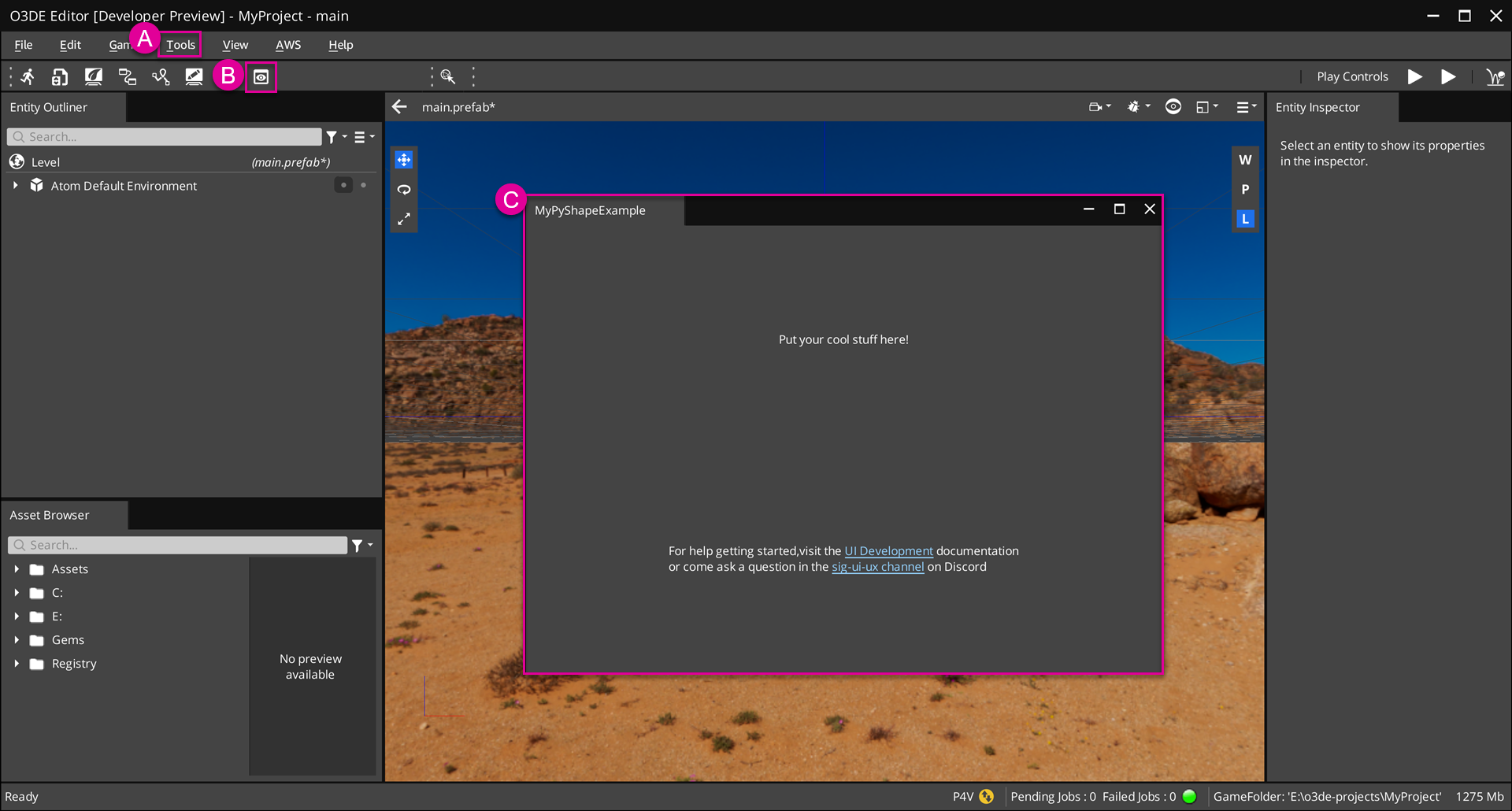
Open the tool by selecting Tools > Examples > MyPyShapeExample from the file menu. (See A in the following image.)
Or, open the tool directly by clicking on the tool’s icon in the Edit Mode Toolbar. (See B.)
Now you can access the Shape Example tool! By default, this tool contains a simple user interface (UI). In the next steps, we’ll design the tool’s UI and code its functionality. (See C.)
Code directory
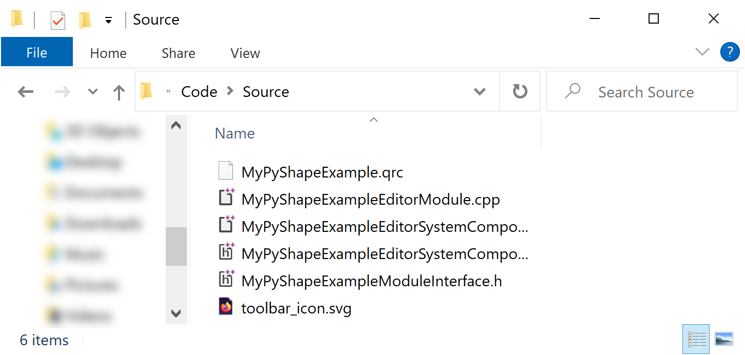
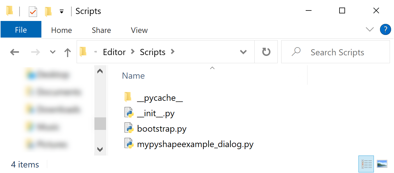
This sections describes your MyPyShapeExample Gem’s code structure. It’s important to become familiar with your Gem’s code structure because this is the entry point where you will program your tool’s custom functionality. In this example, your Gem’s directory is located at: C:\o3de-gems\MyPyShapeExample. This is the path that you specified when you created the Gem. Your Gem’s code is located in the subdirectories Code\Source and Editor\Scripts, which contains the following classes and frameworks that make up your custom tool.
Example of Code\Source directory:
Example of Editor\Scripts directory:
Modules and system components
All Gems have modules and system component classes written in C++ that connect the tool to O3DE and allow it to communicate with other systems. The PythonToolGem template already contains all of the code needed to run the tool in the Editor. You can find these C++ files in Code\Source.
For more information on Gem modules and system components, refer to the Overview of the Open 3D Engine Gem Module system page.
O3DE and Qt frameworks
O3DE extends the Qt framework, so you will use PySide2 —the Python bindings for Qt, Qt for Python —to create a graphical user interface (GUI). You will also use O3DE’s EBuses to communicate with other O3DE interfaces, such as entities and components, and connect them to Qt elements.
You will write most of your tool’s functionality and UI elements in thePyShapeExampleDialog class that’s located in Editor\Scripts\pyshapeexample_dialog.py.
Qt Resources
The
Qt Resource System allows Gems to store and load image files via a .qrc file. This eliminates the need to load image files from absolute paths, making it simpler for you to distribute your Gem. Later, you will store an image file to create an icon for your tool.
Dependent modules
Import the following dependent modules in the Editor\Scripts\pyshapeexample_dialog.py file. The PyShapeExampleDialog class that you will create uses objects from these modules.
import azlmbr.bus as bus
import azlmbr.components as components
import azlmbr.editor as editor
import azlmbr.entity as entity
import azlmbr.math as math

from PySide2.QtCore import Qt
from PySide2.QtGui import QDoubleValidator
from PySide2.QtWidgets import QCheckBox, QComboBox, QDialog, QFormLayout, QGridLayout, QGroupBox, QLabel, QLineEdit, QPushButton, QVBoxLayout, QWidget
Dialogs, Widgets, and layouts
With Qt for Python, you can create a dialogs, or top-level windows. Within a dialog are widgets, which are containers for UI elements, and layouts, which define how those UI elements are arranged. (In comparison, Qt in C++ creates a main widget instead of a dialog.) You custom tool is a dialog that constains sub-widgets of UI elements. Each widget can have its own layout and additional sub-widgets. The nested widget and layout structure allows you to organize groups of UI elements.
The PyShapeExampleDialog class inherits from QDialog, which creates the dialog window. The following instructions walk you through how to set up your dialog’s layout. Be aware that some of the instructions may already be done by the PythonToolGem template.
At the top of your constructor, instantiate a
QVBoxLayoutcalledmain_layout.Later, you will create various UI elements and add them to
main_layout.(Optional) You can add spacing to
main_layoutby usingsetSpacing(...).We recommend that you add a stretch at the bottom of
main_layoutby usingaddStretch()to fill any expanded space when you resize the window.Finally, set
main_layoutto be the layout for this dialog by usingself.setLayout(...).
class PyShapeExampleDialog(QDialog):

    def __init__(self, parent=None):

        main_layout = QVBoxLayout()
        main_layout.setSpacing(20)

        // Add various UI elements to main_layout

        main_layout.addStretch()

        self.setLayout(main_layout)
Input fields and checkboxes
In this step, create an input field for the entity’s name and a checkbox for an option to append a suffix—the component’s name—to the entity’s name. For example, suppose you set the entity’s name to “MyEntity” and enable the checkbox. Then, when you create an entity with a Box Shape component and another with a Sphere Shape component, they will respectively be named “MyEntity_BoxShape” and “MyEntity_SphereShape”.
By the end of this step, your input field and checkbox should look like this:

After instantiating mainLayout, wrap these UI elements in their own sub-widget, set the layout, and add it to the main widget.
To start, instantiate a
QGroupBoxcalledentity_name_widgetand aQFormLayoutcalledform_layout.Later, you will create the input field and checkbox and add them to this widget.
Finally, set the layout of
entity_name_widgettoform_layout, and addentity_name_widgettomain_layout.
        entity_name_widget = QGroupBox("Name your entity (Line Edit)", self)    # 1
        form_layout = QFormLayout()

        # ...                                                                   # 2

        entity_name_widget.setLayout(form_layout)                               # 3
        main_layout.addWidget(entity_name_widget)
Create an input field
An input field takes text input from the user. With Qt, you can create an input field by using the QLineEdit object. In this example, the input field is used to name the generated entity. You will define this behavior later.
Create an input field by instantiating
QLineEdit. In this example, name itname_input.Set the placeholder text in
name_inputby callingsetPlaceholderText(...).Enable a button to clear the text using
setClearButtonEnabled(True).
        self.name_input = QLineEdit(self)
        self.name_input.setPlaceholderText("Optional")
        self.name_input.setClearButtonEnabled(True)
Create a checkbox
A checkbox is an option button that users can enable or disable to trigger a user-defined behavior. With Qt, you can create an checkbox by using the QCheckBox object. In this example, the checkbox controls whether or not to append a suffix to the entity’s name. At runtime, it will start disabled, and enable when the user enters the entity’s name to the input field. You will define this behavior later.
Create a checkbox by instantiating
QCheckBox. In this example, name itadd_shape_name_suffix.Set the checkbox to start in the disabled state by using
setDisabled(True).
        self.add_shape_name_suffix = QCheckBox(self)
        self.add_shape_name_suffix.setDisabled(True)
        self.add_shape_name_suffix.setToolTip("e.g. Entity2_BoxShape")
Add a signal listener with a slot handler
Qt uses signals and slots to communicate between objects (refer to Signals & Slots in the Qt Documentation). Set up a signal listener such that when the user enters text into the input field at runtime, the checkbox automatically enables.
In this example, the signal listener uses a slot handler, which is essentially a Python function that a signal can connect to.
Call
connect(...)to create a connection between the input field (name_input) to the signal (textChanged) and slot (on_name_input_text_changed).self.name_input.textChanged.connect(self.on_name_input_text_changed)Outside of the constructor, define a slot as you would for a standard Python function. In this example, name the slot
on_name_input_text_changed.def on_name_input_text_changed(self, text): self.add_shape_name_suffix.setEnabled(len(text))
Add UI elements to layout
After creating the UI elements—an input field and a checkbox—and connecting a signal listener to them, add them to the UI. To ensure they belong to the sub-widget entity_name_widget, add them to form_layout by calling addRow(...).
        form_layout.addRow("Entity name", self.name_input)
        form_layout.addRow("Add shape name suffix", self.add_shape_name_suffix)
Comboboxes
In this step, you will create a combobox that contains a list of values that you can use to scale the size of the entity.
By the end of this step, your combobox should look like this:

First, wrap these UI elements in their own sub-widget, set the layout, and add it to the main widget.
To start, instantiate a
QGroupBoxcalledcombobox_groupand aQVBoxLayoutcalledcombobox_layout.Later, you will create a combobox and define a list of scale values.
Finally, set the layout of
combobox_grouptocombobox_layout, and addcombobox_grouptomainLayout.
        combobox_group = QGroupBox("Choose your scale (combobox)", self)   # 1
        combobox_layout = QVBoxLayout()

        # ...                                                               # 2

        combobox_group.setLayout(combobox_layout)                           # 3
        main_layout.addWidget(combobox_group)
Create a combobox
A combobox allows users to select an item from a pop up list of items. With Qt, you can create an input field by using the QComboBox object.
Define a list of scale values. In this example, name it
scale_values.Create a combobox by instantiating
QComboBox. In this example, name itscale_combobox.Allow users to enter a custom option in the combobox by calling
setEditable(True).If a user enters a custom option, validate that the value they entered is a numerical value within a specific range and decimal place by calling
setValidator(...). In this example, set the lower bound to0.0, the upper bound to100.0, and the decimal places to3.Add the list of values to the combobox by calling
addItems(...).Add the combobox to
combobox_layoutby callingaddWidget(...).
        scale_values = [                                                            # 1
            "1.0",
            "1.5",
            "2.0",
            "5.0",
            "10.0"
        ]
        self.scale_combobox = QComboBox(self)                                       # 2
        self.scale_combobox.setEditable(True)                                       # 3
        self.scale_combobox.setValidator(QDoubleValidator(0.0, 100.0, 3, self))     # 4
        self.scale_combobox.addItems(scale_values)                                  # 5

        combobox_layout.addWidget(self.scale_combobox)                              # 6
Buttons
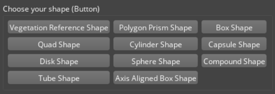
In this step, you will create a collection of buttons that create an entity with different Shape components, such as with a Box Shape, Sphere Shape, Cone Shape, and so on.
By the end of this step, your buttons should look like this:
First, wrap these UI elements in their own sub-widget, set the layout, and add it to the main widget.
To start, instantiate a
QGroupBoxcalledshape_buttonsand aQGridLayoutcalledgrid_layout.Later, you will query for all types of shape components registered with the engine, add buttons to this widget, and add signal listeners to the buttons.
Finally, set the layout of
shape_buttonstogrid_layout, and addshape_buttonstomain_layout.
        shape_buttons = QGroupBox("Choose your shape (Button)", self)   # 1
        grid_layout = QGridLayout()

        # ...                                                           # 2

        shape_buttons.setLayout(grid_layout)                            # 3
        main_layout.addWidget(shape_buttons)
Query Shape components
Query the types of Shape components that’re registered with the engine. In O3DE, all components have a list of provided services that you can query from. In this example, you are looking for Shape components, which all provide “ShapeService”.
Create a component service list called
provided_servicesand add “ShapeService”.Get a list of component types that provide “ShapeService”. Use
editor.EditorComponentAPIBus(...)to callbus.Broadcastand dispatchFindComponentTypeIdsByService, which takes a list of services to include (provided_services) and services to exclude (an empty list) and stores the component types totypeIds.
        shape_service = math.Crc32_CreateCrc32("ShapeService")
        provided_services = [shape_service.value]
        type_ids = editor.EditorComponentAPIBus(bus.Broadcast, 'FindComponentTypeIdsByService', provided_services, [])
Query the names of the Shape components. Later, you will add these name to the buttons.
- Get a list of component names. Use
editor.EditorComponentAPIBus(...)to callbus.Broadcastand dispatchFindComponentTypeNames, takes the list of component types (typeIds) and stores the corresponsing component names tocomponent_names.
component_names = editor.EditorComponentAPIBus(bus.Broadcast, 'FindComponentTypeNames', type_ids)- Get a list of component names. Use
Note:You can query a list of services that components provide by calling the component’sGetProvidedServices()method.
Add buttons
A button is a UI element that the user can click to trigger a user-defined behavior. With Qt, you can create a button by using the QPushButton object. In this example, when the user clicks on the button, it will create an entity with a Shape component. You will define this behavior later.
Loop through the list of component names, create buttons, and add them to the grid_layout. For each component:
Create a button by instantiating
QPushButton. In this example, name itname_input. Pass innameto add the component’s name onto the button.Later, you will connect
shape_buttonto a signal listener.Split
grid_layoutinto three columns, and add the button.
        max_column_count = 3
        for i, name in enumerate(component_names):
            type_id = type_ids[i]

            shape_button = QPushButton(name, self)              # 1

            # ...                                               # 2

            row = i / max_column_count                          # 3
            column = i % max_column_count
            grid_layout.addWidget(shape_button, row, column)
Add a signal listener with a lambda handler
Next, create a signal listener such that when the user clicks the button, an entity will be created in your scene and the corresponding Shape component will be added to that entity.
In this example, the signal listener uses a lambda handler, so you can define the function without defining a slot.
Declare a function
create_entity_with_shape_componentto connect to the signal listener. This function communicates with O3DE’s EBuses, which you will define later.def create_entity_with_shape_component(self, type_id):In the loop that you created earlier, create a connection from the
clickedsignal in theshape_buttonto a lambda function. The lambda function callscreate_entity_with_shape_component(...)and passes in thetype_id.shape_button.clicked.connect(lambda checked=False, type_id=type_id: self.create_entity_with_shape_component(type_id))
Communicate with EBuses
Define CreateEntityWithShapeComponent(...), which communicates with O3DE EBuses to create a new entity with a component specified by the typeId parameter.
Send a request to check if a level is loaded in the Editor by using
editor.EditorRequestBusto callbus.Broadcastand dispatchIsLevelDocumentOpen, which will return true/false if a level has been loaded or not.- Attempting to create an Entity without a level loaded will cause a crash, so if a level isn’t loaded, we will print a warning message and then return.
Send a request to create a new entity by using
editor.ToolsApplicationRequestBusto callbus.Broadcastand dispatchCreateNewEntity, which creates a new entity and returns itsAZ::EntityId. The new entity’sAZ::EntityIdis stored innew_entity_id.If the user entered a name in the input field, update the entity’s name.
Get the name of the entity by calling
text(), and store it inentity_name.If the user enabled the checkbox to apply a suffix of the component’s name to the entity’s name, query the component’s name. Use
editor.EditorComponentAPIBusto callbus.Broadcastand dispatch theFindComponentTypeNamesevent, which finds the component names of the provided list and stores them incomponent_names.Format the name and suffix, if any.
Use
editor.EditorEntityAPIBusto callbus.Eventand dispatch"SetName"to set the name ofnew_entity_idtoentity_name.
Set the entity’s scale.
Get the value in the combobox by calling
currentText(), and store it inscale_text.Set the entity’s scale by using
components.TransformBusto callbus.Eventand dispatch"SetLocalUniformScale", which sets the scale ofnew_entity_id. Be aware that you must convertscale_textto a float.
Add a Shape component to the entity. Use
editor.EditorComponentAPIBusto callbus.Broadcastand dispatch"AddComponentsOfType", which adds the components from the provided list tonew_entity_id.
     def create_entity_with_shape_component(self, type_id):

        # 1
        is_level_loaded = editor.EditorRequestBus(bus.Broadcast, 'IsLevelDocumentOpen')
        if not is_level_loaded:
            print("Make sure a level is loaded before choosing your shape")
            return

        # 2
        new_entity_id = editor.ToolsApplicationRequestBus(bus.Broadcast, 'CreateNewEntity', entity.EntityId())

        # 3
        if self.name_input.text():
            entity_name = self.name_input.text()

            if self.add_shape_name_suffix.isChecked():
                component_names = editor.EditorComponentAPIBus(bus.Broadcast, 'FindComponentTypeNames', [type_id])

                shape_name = component_names[0]
                shape_name = shape_name.replace(" ", "")

                entity_name = f"{entity_name}_{shape_name}"

            editor.EditorEntityAPIBus(bus.Event, "SetName", new_entity_id, entity_name)

        # 4
        try:
            scale_text = self.scale_combobox.currentText()
            components.TransformBus(bus.Event, "SetLocalUniformScale", new_entity_id, float(scale_text))
        except:
            pass

        # 5
        editor.EditorComponentAPIBus(bus.Broadcast, "AddComponentsOfType", new_entity_id, [type_id])
Icon
An icon is an image file that’s used to represent your tool in the Editor. The icon appears in the Edit Mode Toolbar in the Editor (see the following image).
Add an icon
The following instructions walk you through how to store the icon using the Qt Resource System and load it from your Gem module. Be aware that some of the instructions may already be done by the PythonToolGem template.
Add an image file to the
Code\Sourcedirectory to use as your icon. In this example, the icon is namedtoolbar.svg. We recommend that your icon adheres to the guidelines in UI development best practices .Add your icon to MyPyShapeExample Gem’s resources by updating
Code\Source\ShapeExample.qrcwith your new icon’s file name.<!DOCTYPE RCC><RCC version="1.0"> <qresource prefix="/MyPyShapeExample"> <file alias="toolbar_icon.svg">toolbar_icon.svg</file> </qresource> </RCC>Register MyPyShapeExample Gem’s resources to Qt Resource System by adding the following code in
Code\Source\EditorModule.cpp.Define the function
InitShapeExampleResource()and callQ_INIT_RESOURCE(...)to register the Qt resrouces listed inShapeExample.qrc.void InitShapeExampleResources() { Q_INIT_RESOURCE(ShapeExample); }Call
InitShapeExampleResource()in theEditorModuleclass’s constructor.
Build and test your tool
You can test your custom tool by running it from the Python Scripts panel in the Editor.
Open Editor for your project.
Open the Python Scripts panel by selecting Tools > Other > Python Scripts from the file menu.
Open
pyshapeexample_dialogin the Python Scripts panel.
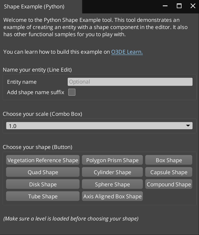
Congratulations! You created a custom tool Gem that’s written in Python, built it, and loaded it in the Editor. Your Shape Example tool should look something like this:
Download the PyShapeExample Gem sample
Now that you’ve completed this tutorial, you can compare your MyPyShapeExample Gem to the sample, PyShapeExample Gem, in
o3de/sample-code-gems repository .
To download this sample and load it in the Editor:
Download or clone the repository. The PyShapeExample Gem is located in
<repo>\sample-code-gems\py_gems\PyShapeExample.git clone https://github.com/o3de/sample-code-gems.gitBefore you can open the Shape Example tool, do the following:
Register your Gem.
Enable it in your project.
Rebuild your project.
Open the tool in the Editor.
These steps are explained earlier in this tutorial. Refer to Create a Gem from the
PythonToolGemtemplate.
