Creating Blend Trees
In the Animation Editor, an animation graph consists of nodes and connections that define transitions and the way that data is passed between nodes. The Animation Editor supports state machines and blend trees.
A blend tree is a collection of nodes with input and output ports that are color coded by data type and read from left to right. Input ports appear on the left side of the nodes and output ports appear on the right. The blend tree outputs the pose that is connected to the Final Node, which is included in every blend tree and cannot be deleted. If you choose not to connect a node to Input Pose, the Final Node outputs a bind pose.
To create a blend tree
In O3DE Editor, choose Tools, Animation Editor.
In the Animation Editor, on the Anim Graph tab, click the + icon to create an animation graph.
Click the Save icon. Navigate to the directory where you want to save your animation graph. Type a name for your file and then click Save.
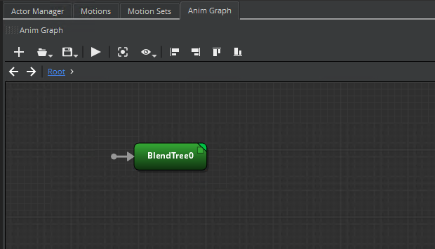
In the center pane, on the Anim Graph tab, right-click the grid and then choose Create Node, Sources, Blend Tree.

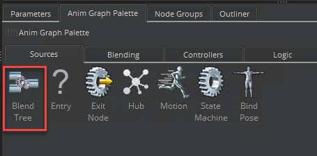
Alternatively, in the Anim Graph Palette, on the Sources tab, drag Blend Tree into the animation graph.

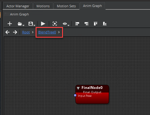
- Double-click the blend tree node that you created. When you double-click the node, a new link appears above the animation graph with the node name. The Final Node also appears.

Do the following to add nodes and connections:
In the animation graph, right-click the grid and choose Create Node. Choose a node from the following categories:
- Sources
- Blending
- Controllers
- Logic
- Math
- Misc
Repeat step 6a to add more nodes to your blend tree.
Connect the nodes by dragging inputs to outputs. Note the following color cues:
- Gray - Dashed gray helper lines indicate the ports that you can connect to.
- Green - The connection curve turns green when it’s okay to release the mouse button.
- Red - The connection curves turns red when the connection is not allowed.
- Yellow - The connection curve turns yellow in transition states, such as when you drag a connection between ports.
Topics
